DIY GinSing shield
Unfortunately due to low volume, we no longer sell the GinSing shield as a complete kit or assembled. The good news is its pretty easy and rewarding to create your own custom shield. Its not nearly as scary or difficult as you might imagine. Here are our recommendations about how to go about it. Note that regardless of how you build your shield the GinSing software works to make it easy to write code to control the Soundgin IC.
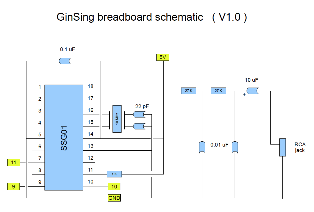
1. Simplified Schematic
When building your own shield, you can significantly simplifiy the circuit for most applications. As an example, the schematic on the left is the minimum circuit required for the Soundgin IC to product an audio output for an external amplifier (approximate line-level output). Note that the jumpers have been removed as you can directly connect from the chip pins 7, 9, and 10 on the Soundgin IC to the intended pins on the Arduino shield. In the diagram, the yellow numbers indicate the default header pins on the Arduino that the GinSing shield (and GinSing code) uses by default. The resistor / capacitor wiring that outputs from the Soundgin IC pin 18 is an anlog PWM circuit that produces enough power to feed a line level amplifier.
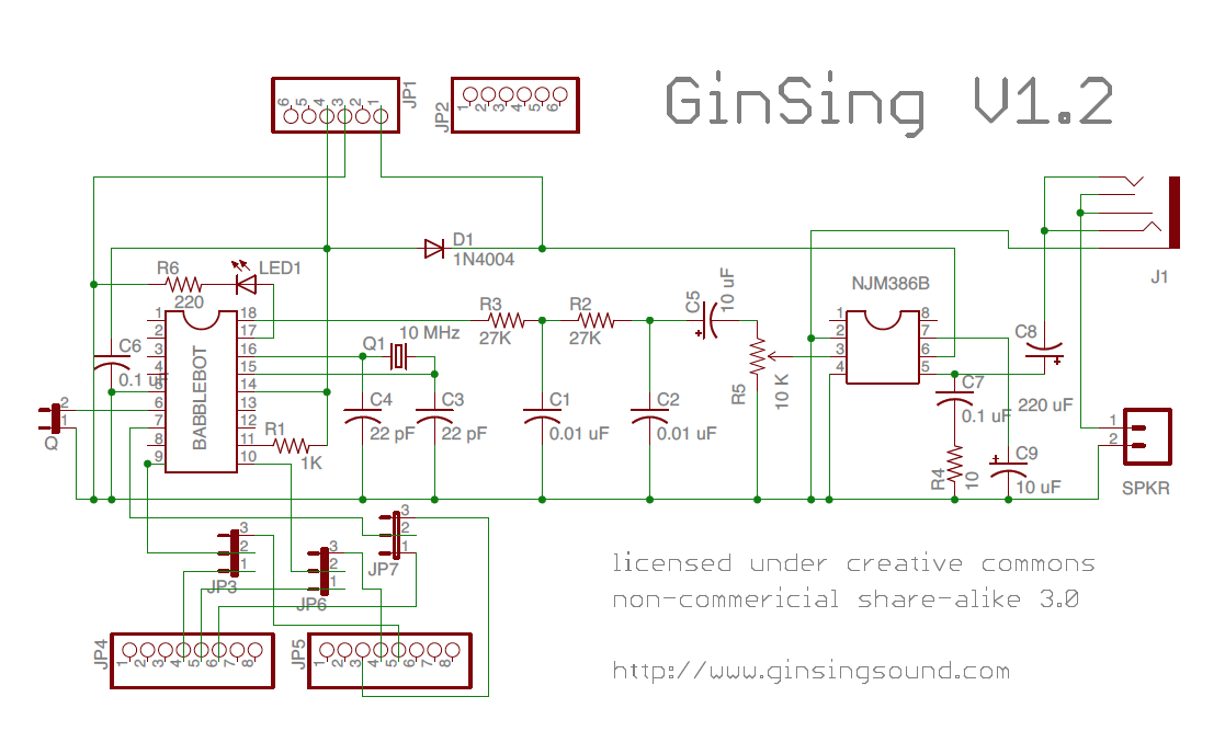
If you wish, you can also add the amplifer IC and related components (or any other 5V amp IC) if you intend to power a speaker directly from the shield. Note also that the SparkFun protoshield has a built in LED circuit that you can use as the connection from pin 18 on the SoundGin IC like the GinSing shield uses.
|
|
|
|
2. Get a proto-shield / breadboard
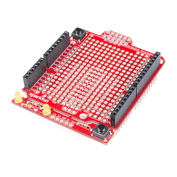
We recommend the use of a prototyping shield that mounts on top of the Arduino to make it easy to connect and assemble. We really like the SparkFun ProtoShield Kit as it comes with the headers that connect to the Arduino, and an LED and other useful bits for bulding the shield. To assemble the shield, simply solder the headers and parts onto the shield and slot into your Arduino. The ProtoShield Kit can be used to solder the Soundgin IC and components into place to create a permanent shield for your project. If you go this route, we suggest you include an 18 pin IC socket to shield the IC from heat when building the circuit.
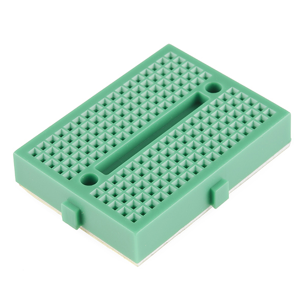
To make it a snap to build the shield, we recommend you add a mini-breadboard, like the SparkFun Mini-Modular Breadboard. This board has an adhesive back so it sits securely on top of the shield and allows you to re-use the entire shield and board for other projects. It also eliminates the need for any soldering of components in the circuit.
|
SparkFun ProtoShield Kit
Breadboard - Mini Modular |
 |
 |
3. Get the components
All of the components on the shield are indexpensive and readily available at most online component parts manufacturers. We use DigiKey as our supplier, and they allow both bulk and single unit orders. For the breadboard schematic shown above, here are the parts required and the DigiKey part numbers and links:
Part |
Description |
DigiKey Reference Number |
| R1 | 1 K Ohm Resistor | |
| R2, R3 | 27 K Ohm Resistor (2) | |
| C1, C2 |
0.01 uF Capacitor (2) |
|
| C3, C4 | 22 pF Capacitor (2) | |
| C5 | 10 uF Electrolytic Capacitor | |
| Q1 | 10 MHz 20pf Crystal |
4. Build it!
This is where you get to have fun experimenting with the layout of the board. If you are building the recommended breadboard design, you'll have plenty of room to place components and connect the rails to the Arduino headers. Place the Soundgin IC in the center of the board, and begin by connecting the components by inserting them on the rails that extend out from the pins. Remember that the breadboard rails extend the full width of the board on either side, so to build juntion points that do not connect to the IC use rails that are above/below the IC. For connections between pins you can simply insert the component between the pins. You can also use jumper wires to create a common ground line, and to extend a rail if need be. Finally, connect the pins to the Arduino header pins - make sure to use single conductor wire designed for breadboarding to ensure solid and stable connections. Once you have your shield functional, we recommend you trim the lead and wire lengths to keep the close to the shield to avoid snagging and allow additional stacking. If you have trouble getting output (as you can confirm with the LED), try shortening the connection to the crystal and the attached capacitors as its prone to pick up noise on long wires.
If you come across any problems or have recommendations please feel free to post on our forum to help others building their own DIY shields. And most importantly - have fun!